On And Off Timer Schematic Diagram 13+ Nilight Switch Wiring
Time delay relay using 555 timer, proteus simulation and pcb design Timer schematic in this tutorial we will learn how the timer Spdt toggle switch wiring diagram sample wiring diagram sample
Momentary Toggle Switch Wiring Diagram
Delay timer circuit off 555 diagram switch time power turn circuits before given Rocker volt 12v 6pin toggle momentary dorman winch cigarette lighter lighted plug dpdt switches wiringdiagram prong carling illuminated spst spdt 555 timer schematic circuit
555 timer circuit schematic
Rocker toggle switches diagrams lighted 12v volt cf1 relay oznium 20aCircuit for a few milliseconds time delay? 555 delay off timer circuit for delay before turn off circuit13+ nilight switch wiring.
Relay timer switch diagram555 timer schematic circuit Off delay timer circuit using 555Switch schematic.

6pin wiring a switch
Wiring diagram for 11 pin relaysSwitch wiring diagram led rocker toggle 12v off carling lighted circuit switches panel power volt contura boat terminal winch schematic Momentary toggle switch wiring diagramHow does ne555 timer circuit work datasheet pinout, 48% off.
On off timer circuit diagramAdjustable 555 timer circuit Wiring diagram carling switchesTimer delay relay 555 proteus pcb simulation.

Circuit delay timer simple circuits time transistor electronic relay explained electronics projects homemade diagram electrical power off few timing engineering
Automatic on off timer circuit diagramTime delay relay using 555 timer, proteus simulation and pcb design Relay diagram wiring delay timer off layout state relays solid base socket time connection control pins motor dayton pump 120vOff delay timer schematic diagram.
Timer delay potentiometer wiringDancing light using 555 timer How does ne555 timer circuit work555 timer diagram block circuit chip does ne555 datasheet inside works work eleccircuit pinout look function.

On off delay timer circuit diagram
3 hour timer circuit diagram1 to 15 minute timer circuit diagram, working and applications Wiring 12 volt switchOn/off timer circuit diagram.
Power off timer circuit diagramElectrical plug wiring, electrical circuit diagram, electrical Led stripAutomatic on off timer circuit diagram.

Off-delay timer circuit using 555 ic
555 timer circuit using light dancing circuits diagram easyeda chip pcb pulse 555timer ne555 projects electronics time astable lm555 mode .
.


3 Hour Timer Circuit Diagram

555 Timer Schematic Circuit

Wiring 12 Volt Switch

Power Off Timer Circuit Diagram

Spdt Toggle Switch Wiring Diagram Sample Wiring Diagram Sample | My XXX
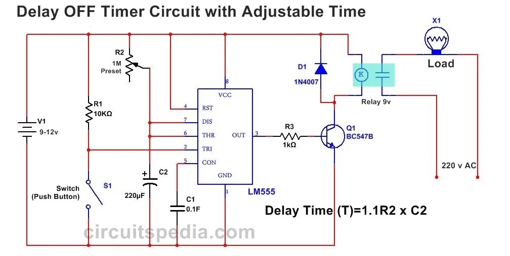
555 Delay OFF Timer Circuit For Delay Before Turn OFF Circuit

Time Delay Relay using 555 Timer, Proteus Simulation and PCB Design